Demo #2: Final Demo of Working System Integrated Onto PCB

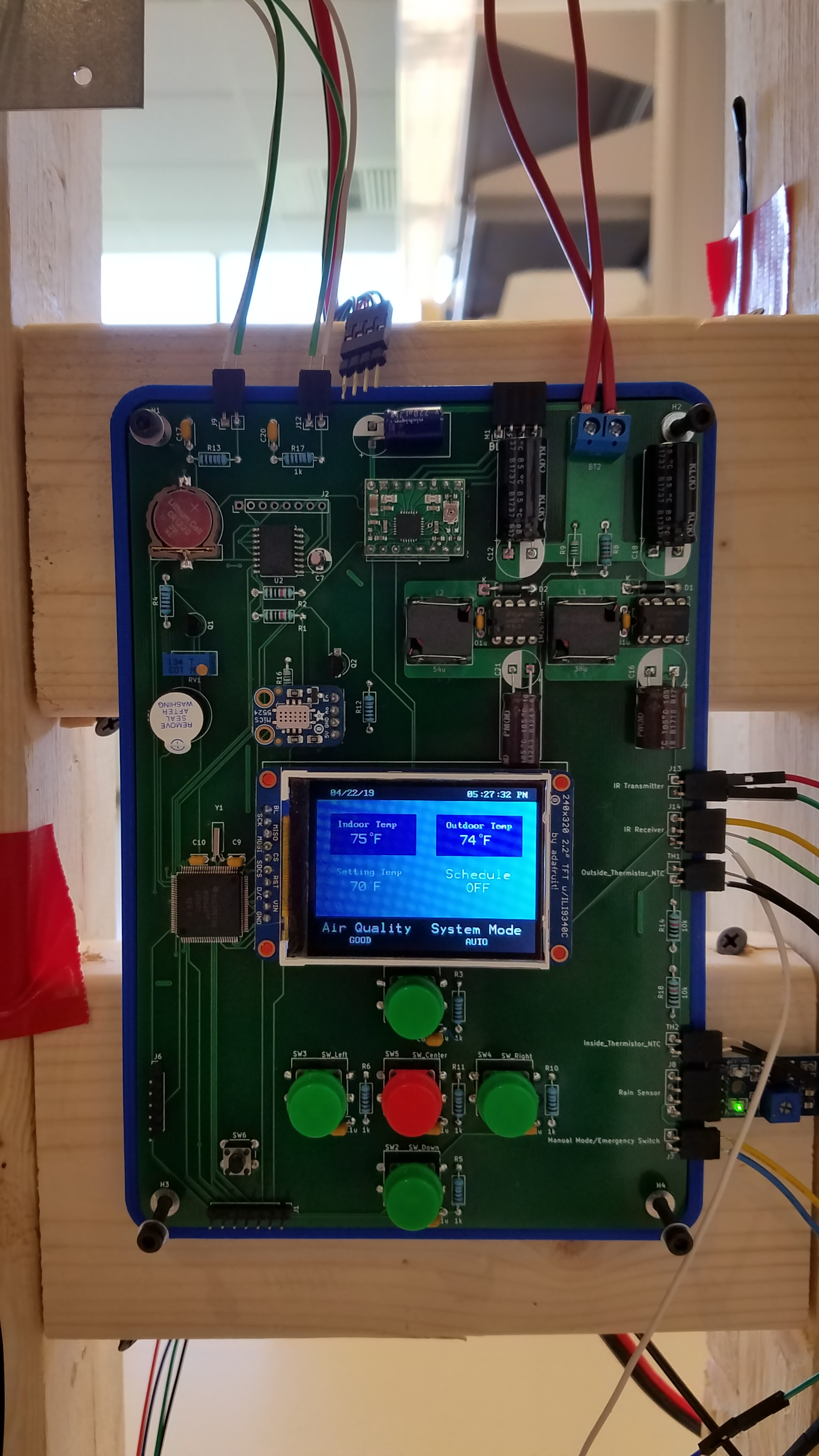
This is our second and likely final demo of our project working with the vast majority of its functionality. The biggest jump from the last demo was integrating our entire system’s components (MSP430, sensors, passive components, power regulation, etc.) onto a PCB. Here is a close-up of the PCB without the front cover of the case:

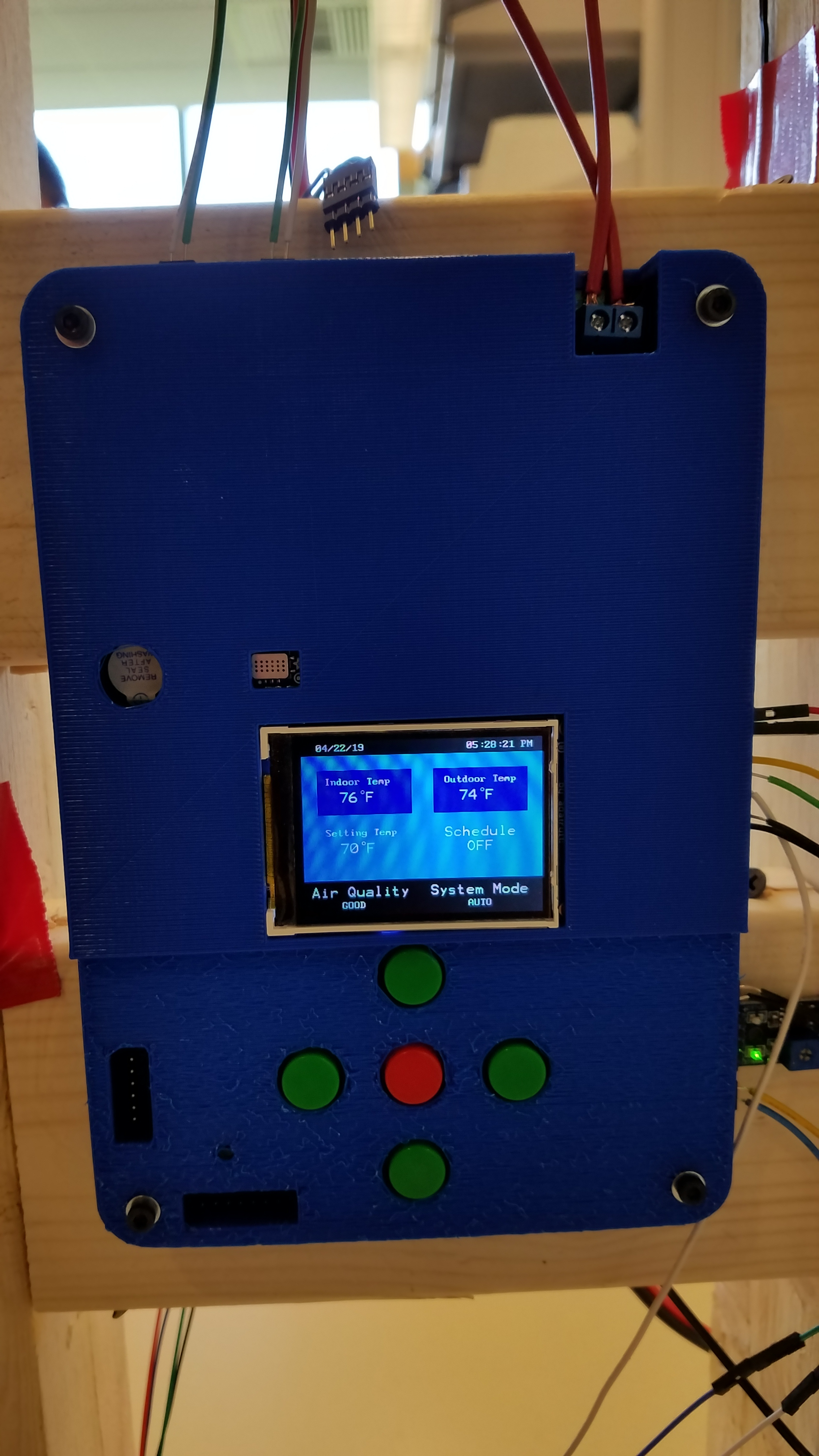
And here is a picture of the PCB with the front cover of the case:

In addition to integrating our system onto a PCB, we also were able to do the following major upgrades since the last demo:

  1. 3D printed a stiffer mount for the stepper motor and lighter handle to be used for manual operation.
  2. Successfully integrated sensor logic with our GUI and calendar system
  3. Mostly fixed the stepper motor stalling issue by decreasing acceleration to top speed (currently occasionally stalls, but that’s mainly due to the window starting to wear out from our repeated opening/closing, so it gets stuck from time to time).

The only feature remaining that we may or may not be able to finish before final presentation is the scheduling system/calendar. Presently you can navigate the calendar/scheduling system just fine, however the scheduled blackout periods don’t actually take effect in the back end of the software. If we are able to resolved this before final presentation, we will likely shoot another demo showing that feature, otherwise it will remain as an opportunity to expand the system in the future if desired.

Demo #1: Preliminary System Test of Most Functionality

This was our first test of the majority of our system completely hooked up and running. It shows the window opening and closing based on temperature differences, air quality, rain, and obstruction detection. We have designed a PCB to encapsulate all our components, but it won’t arrive until after we shot this video, so for this preliminary demo, everything was on breadboard (which of course made it extremely messy with all the wires). The things that worked well and we were happy with their performance:

  1. Motor opened and closed window per the readings from the temperature sensors as it should.
  2. IR Obstruction sensor worked as expected (minus interference from the sun, which we will correct by next demo).
  3. Air quality sensor opened the window when it should.
  4. Rain sensor closed the window when it should.
  5. Emergency switch/manual mode worked as it should.
  6. Power supply regulated our 12V battery to power all our sensors as it should.
  7. Limit switches made the window open/close at the correct positions.

Things we want to do or improve by the time we do our final demo:

  1. Motor occasionally stalls when trying to begin opening/closing window.
  2. Transfer entire system to PCB when it arrives.
  3. Refine temperature code for opening/closing window (it works but we can improve its logic).
  4. Fully incorporate GUI/scheduling functionality with the basic GUI seen in the video.
  5. 3D print “lenses” to block sunlight from IR obstruction detectors so only the light from the IR LED reaches the IR photo-diode.
  6. 3D print a more stable motor mount to make the motor experience less friction when trying to move (hopefully solve the stalling issue in the process).
  7. 3D print a handle for manually cranking the motor from the user’s side.

Prototyping Update #2: Stepper Motor

In this update, we successfully configured the MSP430FR6989 Launchpad evaluation board to communicate with an A4988 stepper driver to run a NEMA 11 stepper motor. The stepper motor has a 27:1 gearbox on the output, which results in the input shaft having to turn about 27 times before the output shaft can complete a full rotation. The basic principle of operation for this setup is that the MSP430 sends a PWM signal to the A4988, and every pulse received turns the stepper motor 1.8° (assuming a feature called micro-stepping isn’t on, which it wasn’t for this test). The higher the frequency of the PWM signal, the faster the motor will turn.

Although we used an A4988 stepper driver in this test, we’re currently testing two other stepper drivers as well (one of which has several more advanced features), but the reason we tested with an A4988 first was because it is a simple and reliable drive, and we had faster access to it than the other stepper drivers. Although the other drivers have slightly different feature sets, the basic principle to use them all is the same, therefore the majority of the code for the MSP430 will work between the three drivers with minimal differences.

For this test, we are using 9V from a 9V battery to power the motor, but in our final project, we will power the motor from a 12V battery. This higher voltage will allow for faster motor speeds without losing precision of movement. The primary function for the motor in the final project will be to open and close the window.

There is also a switch connected to the active-low enable pin of the A4988. When this switch is on, the enable pin is shorted to ground, enabling the output of the stepper driver to the motor. However, when the switch is off, the enable pin is pulled high by a 10 kΩ pull-up resistor connected to Vcc (3.3V for the MSP430). This consequently disables the stepper driver output to the motor, ceasing its movement. This simple add-on circuit was meant to test our emergency shutoff/manual window operation switch that we will have on the final project. It performed exactly as expected, so we see no problems using it for the emergency shutoff/manual operation switch.

Prototyping Update #1: SPI LCD and Analog Sensor

For this update, we successfully setup the MSP430FR6989 Launchpad evaluation board to read voltages from an analog sensor, in this case a light-dependent resistor (LDR), and display information on an LCD using SPI.

For the analog sensor, we setup a simple voltage divider circuit between the LDR and a 1 kΩ resistor. The MSP430 uses a 12-bit ADC, so the quantized value is 12 bits or 4 hexadecimal digits to save space on the display. As is seen in the video, as the hand got closer to the LDR, the measured light level decreased, and vice-versa. This test was significant because for the final project, we will be using thermistors, which are simply resistors that change resistance based on temperature, and the circuit for those will be identical to the LDR voltage divider circuit. The only real difference will be in the software, as thermistors require some additional calculations to convert the voltage to a temperature.

For the LCD, we used a graphics library to perform most of the screen rendering instructions through SPI. For this test, we simply displayed the light level value from the LDR in plain text, but this is enough to confirm the proper setup of the library and SPI commands. For the final project, we aren’t using this exact display, but rather one that’s about 0.5″ bigger. The graphics library we used for this smaller display also works with the larger display, the only difference is changing a few parameters such as screen resolution.